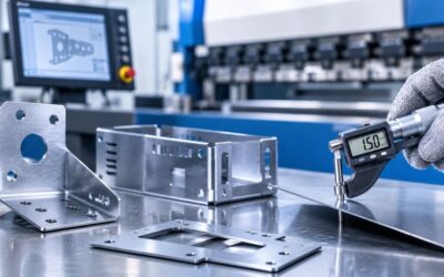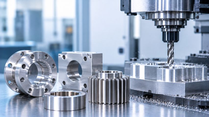
A vertical machining center (VMC) can hold tight tolerances on complex parts, yet milled components still fail inspection more often than buyers expect. The cause rarely sits in the machine itself. It usually sits in fixturing, tool selection, programming, or inspection practice. For procurement teams comparing any CNC manufacturer in India, knowing where VMC machining goes wrong is the fastest way to judge a supplier.
What VMC Machining Actually Does to a Workpiece
VMC machining sits at the center of most precision milling work. Buyers who understand its basic mechanism ask sharper questions at the quotation stage. This explains how a vertical machining center removes material, which machine elements govern accuracy, and why the same machine model can produce very different results in two different factories.
How a Vertical Machining Center Removes Metal
VMC machining is a CNC milling process in which a vertically oriented spindle rotates a multi-point cutting tool. The tool moves along programmed X, Y, and Z axes, removing material from a fixed workpiece. The result is flat faces, pockets, slots, holes, and contoured profiles cut to a digital drawing. CNC stands for computer numerical control. A coded program, usually written in G-code, tells the machine where to move and how fast. Each line sets a position, a feed rate, or a spindle speed. The machine then repeats that sequence identically on every part in a batch.
The workpiece stays clamped to the machine table while the tool cuts. This differs from turning, where the part rotates against a stationary tool. Because the part does not spin, a VMC can machine prismatic shapes such as blocks, plates, housings and brackets. An automatic tool changer swaps end mills, drills, taps and face mills mid-cycle without operator handling. One setup can therefore face, pocket, drill and tap several features in sequence. In general industry practice, fewer operator interventions mean fewer chances for positional error between features. That consistency explains why buyers specify VMC work for multi-feature parts.
The Machine Elements That Decide Accuracy
Four machine elements set the ceiling on what any VMC can achieve. The spindle determines speed range, torque, and runout, the small wobble of a rotating tool. Linear guideways and ball screws determine how precisely each axis reaches its commanded position. Table size and axis travel limit the largest part the machine can hold. The controller interprets the program and manages acceleration through corners. A buyer rarely needs every figure, but travel envelope and spindle speed matter for large or hard-material parts. Asking for these figures early prevents a quote for a part the machine cannot physically fit.
Machine specification sets the ceiling, not the result. Two factories running identical VMCs can deliver very different scrap rates on the same drawing. The gap comes from machine condition, calibration frequency, and the discipline of the people running it. A worn ball screw, for example, adds backlash, meaning lost motion when an axis reverses direction. That error shows up as hole positions drifting from drawing values. Attri Tech Machines lists VMC machining within its manufacturing capabilities and product range. Buyers should request current calibration records alongside any capability statement.
How Multi-Axis Movement Shapes What a VMC Can Cut
Axis count decides which features a VMC can reach in one clamping. Each additional axis reduces setups, but it also adds programming complexity and new sources of error. Buyers who understand this trade-off can judge whether a supplier’s proposed setup suits their part or introduces avoidable positional risk.
Three-Axis Motion and Its Practical Limits
A three-axis VMC moves the tool along X (left-right), Y (front-back), and Z (up-down). The tool always approaches from directly above the workpiece. This suits any feature visible from the top face: pockets, through-holes, slots, steps, and two-dimensional profiles. Most prismatic parts in general engineering fall comfortably into this category. Three-axis machines also program quickly and hold position well, because fewer moving elements contribute error. For a bracket, manifold plate, or fixture base, a three-axis VMC is usually the most cost-efficient route to a conforming part.
The limit appears when features sit on more than one face. A hole on the side of a block cannot be reached from above. The operator must unclamp the part, rotate it, and clamp it again. Every re-clamp introduces a new reference position, and small location errors accumulate between faces. A part with features on four sides may need four setups, each adding handling time and positional risk. In general industry practice, cross-face positional tolerances are where three-axis work most often falls short. Buyers should check how many setups a supplier plans before accepting a quote on multi-face parts.
What a Fourth Axis or Rotary Table Adds
A fourth axis adds rotation, usually through a rotary table or indexer mounted on the main table. This axis, often called the A-axis, turns the workpiece around a horizontal centreline. The machine can then present several faces to the spindle without unclamping the part. Features on four sides share one reference position. That keeps cross-face hole positions and perpendicularity under tighter control. Indexing, where the table rotates to a fixed angle and locks, is the most common use. Continuous four-axis work, cutting while rotating, produces helical grooves, cam profiles and wrapped features.
Extra axes bring their own failure points. A rotary table must be trammed, meaning aligned precisely, to the machine’s linear axes. If its centreline sits slightly off, every rotated feature inherits that offset. Programming also becomes more demanding, because computer-aided manufacturing (CAM) software must calculate tool positions relative to a moving part. Five-axis machines add a second rotary axis for simultaneous compound angles. Buyers should confirm the actual axis configuration a supplier will use, rather than assuming one from the term VMC. Attri Tech Machines’ published material lists VMC machining without stating axis count, so request this detail directly.
Complex Geometries That Call for Vertical Milling
Vertical milling earns its place on parts with geometry that a lathe cannot produce. These same features carry the highest scrap risk. Understanding which geometries stress the process helps buyers flag critical dimensions on the drawing. It also helps suppliers plan the right tools and sequence before the first chip is cut.
Pockets, Slots, Contours and Hole Patterns
Most VMC work involves four feature families. Pockets are enclosed recesses machined into a face, such as a valve body cavity, the kind of feature found in CNC hydraulic valve component work. Slots are open-ended channels used for keys, guides, or clearances. Contours are curved outer or inner profiles cut by moving two or three axes together. Hole patterns include drilled, reamed, bored, and tapped holes positioned to a datum. Each family stresses the process differently. Pockets test tool reach and chip evacuation, while hole patterns test positional accuracy across every hole at once.
Hole patterns deserve particular buyer attention. A drawing may call for true position, a geometric tolerance that limits how far a hole’s center may stray from its ideal location. Drilling alone rarely achieves tight true position, because drills wander slightly on entry. Precision holes therefore usually follow a sequence of spot drilling, drilling, then reaming or boring. Reaming uses a multi-flute tool to bring a hole to final size and finish. Boring uses a single-point tool to correct both size and location. Buyers should mark which holes are functional, so suppliers apply the slower, more accurate sequence where it counts.
Thin Walls, Deep Cavities and Tight Internal Corners
Thin walls flex under cutting force. The tool pushes the wall away, cuts less material than programmed, and the wall springs back. The finished wall then measures thicker than the drawing allows. Experienced programmers counter this with lighter finishing passes, alternating sides and leaving support material until late in the cycle. Deep cavities create a different problem. A long tool must reach into the pocket, and deflection rises sharply with overhang. In basic beam mechanics, deflection grows with the cube of stick-out length. Doubling the reach can increase deflection about eightfold under the same cutting load.
Internal corners add a constraint many first-time buyers miss. A rotating end mill always leaves a radius equal to its own radius in a vertical internal corner. A perfectly sharp inside corner is not achievable by milling alone. Drawings demanding sharp corners force a choice: accept a radius, add relief cuts, or route the feature to another process. Small corner radii also force small, fragile tools that cut slowly and break more easily. Specifying the largest radius the design allows usually shortens cycle time and reduces breakage. That single drawing change often lowers unit cost more than any price negotiation.
Discuss a Milled Part With the Engineering Team
Ask Attri Tech Machines’ engineering team to review any feature on your milled part that looks risky. With the drawing and material in hand, the team can say how it would hold and check that feature. Send your requirements through the online inquiry form.
Fixturing and Setup: The Most Common Point of Failure
Many milled parts fail inspection before a single tool touches them. The cause lies in how the part is held and referenced. Fixturing errors are hard to see during machining and often surface only at inspection, sometimes after an entire batch is complete. That makes setup discipline the first thing to question in any VMC supplier.
How Clamping Distorts a Part
Clamping force holds the part against cutting loads, but it also bends the part. A thin plate clamped at its corners can bow slightly upward in the middle. The tool then faces that bowed surface flat. Once the clamps release, the plate springs back, and the machined face is no longer flat. The error appears only after unclamping, so that on-machine checks can miss it entirely. Over-tightened vice jaws cause the same problem on slender parts. Skilled setters place clamping points directly over solid support and apply only the force the cut actually needs.
Material condition adds a second layer to this problem. Bar stock and plate often carry residual stress from rolling, forging, or heat treatment. Removing large volumes of material releases that stress, and the part moves. A pocketed aluminum plate may twist after heavy roughing, even with perfect clamping. Good practice roughs the part, releases the clamps, lets it relax, then re-clamps lightly for finishing. This adds a step but protects flatness. Buyers specifying tight flatness on heavily machined parts should ask whether the supplier’s process includes this sequence. Its absence is a frequent hidden cause of rejected batches.
Datum Mismatch Between Drawing and Machine
A datum is the reference surface, edge, or hole from which a drawing measures other features. The machine needs its own zero point, called the work offset, set from physical surfaces on the part. Problems begin when the operator sets the work offset from a different surface than the drawing’s datum. Every feature then measures correctly, but relative to the wrong reference. The parts look accurate on the machine and fail at incoming inspection. In general industry experience, this mismatch ranks among the most common reasons an entire batch fails on positional tolerance.
The fix starts at drawing review. A supplier should read the datum scheme before programming and set up from the surfaces the drawing specifies. Where a casting or rough blank offers no reliable datum, the first operation should machine one. That first-operation face or bore then anchors all later features. Buyers can reduce risk by declaring datums explicitly using geometric dimensioning and tolerancing, often shortened to GD&T. A recurring pattern at the quotation stage is drawings with dimensions chained edge to edge and no declared datum. Clarifying the reference scheme before production prevents disputes over which measurement is correct.
Tooling, Cutting Conditions and Heat Effects
Once a part is held correctly, the cutting tool becomes the next major variable. Tool condition, cutting parameters, and heat gradually shift dimensions during a run. These errors rarely show on the first part. They appear as drift across a batch, which is why buyers should ask how suppliers control them over time.
Tool Deflection, Wear and Chatter
Every cutting tool bends slightly under load. That deflection leaves walls tapered and features undersized or oversized, depending on cut direction. Shorter, stiffer tools reduce the effect, so tool selection matters as much as programming. Wear compounds the problem over time. As the cutting edge dulls, cutting force rises and the tool deflects further. A finish pass that measured correctly on part one may drift by part fifty. Solid carbide end mills generally resist wear better than high-speed steel on harder materials. Coatings such as titanium aluminum nitride extend tool life further in many steel applications.
Chatter is a self-sustaining vibration between tool and workpiece. It leaves a visible wavy pattern on the surface and can chip cutting edges. Chatter usually results from excessive overhang, weak clamping, or a spindle speed that excites the system’s natural frequency. Changing speed, shortening the tool, or adding support usually cures it. The risk for buyers is that a supplier may hide chatter marks with an unrecorded polishing step. That step can alter critical dimensions without appearing on the process sheet. Buyers specifying finish should state the required Ra value (average surface roughness) in microns.
Heat, Spindle Growth and Dimensional Drift
Machining generates heat in the tool, the part, and the machine itself. A steel part warmed by cutting measures differently once it cools to room temperature. Steel expands roughly 11 to 13 microns per meter for each degree Celsius of temperature rise. On a 300 mm part, a 5°C rise shifts length by about 16 to 20 microns. That shift can consume most of a tight tolerance band. Coolant controls part temperature and clears chips from the cut. Measuring parts only after they return to ambient temperature avoids both false passes and false rejections.
The machine also grows as it warms. A spindle running at high speed for an hour expands along its own axis. That expansion shifts Z-axis depth on every feature cut afterward. Machine structures also respond to shop temperature swings between a cool morning and a hot afternoon. In general industry practice, well-run shops warm up spindles before precision work and periodically re-check tool offsets. Shops in hot climates without temperature-controlled bays face this challenge more sharply. Buyers with tight depth or flatness tolerances should ask how the supplier manages warm-up and where critical features are measured.
CAM Programming and Process Planning Decisions
Programming decides the order, path, and speed of every cut. Two programmers can produce conforming parts with very different cycle times, surface finishes, and scrap rates. Most of these decisions stay invisible to buyers, yet they shape unit cost and batch consistency. Knowing what sound process planning looks like helps buyers critically evaluate a supplier’s quotation.
Toolpath Strategy and Machining Sequence
CAM software converts a 3D model into toolpaths, the exact routes each cutter follows. Strategy choice affects tool load, heat, and finish. Adaptive or trochoidal roughing keeps tool engagement constant, which reduces load spikes. Conventional pocketing can plunge a tool into full-width cuts, raising deflection and wear. Finishing passes then remove a thin, even layer left after roughing. Leaving a consistent finishing allowance, typically a few tenths of a millimeter in general practice, lets the final pass hold size reliably. Uneven stock left for finishing is a quiet cause of size variation across one feature.
Sequence matters as much as path. Heavy roughing should generally finish before precision features are cut, so stress release does not move finished surfaces. Holes that locate a mating part are often bored last, after the part has settled. Features referenced from one datum should be cut in the same setup wherever possible. A common buyer question at quotation stage is why two suppliers quote very different cycle times. Sequence and strategy usually explain the gap. An aggressive cycle may carry hidden scrap risk, while an over-cautious plan inflates unit cost without improving conformance.
Prove-Out Before Committing to Production
Prove-out is the controlled first run of a new program. The operator runs it at reduced feed rates and checks each operation before trusting full speed. Many shops also simulate the program in software, checking for collisions between tool, holder, fixture, and part. Simulation catches gouges and crashes but cannot predict deflection, chatter, or thermal movement. Only cutting real material reveals those effects. A careful prove-out measures the first part completely, adjusts tool offsets, and repeats until every dimension conforms. This step consumes time and material, which explains why first-off parts cost more than repeat production.
Rushing prove-out is a common shortcut under delivery pressure. The risk is a program that produces conforming parts only on a fresh tool or a cool machine. Problems then appear partway through the batch. Buyers can protect themselves by asking for the first-off inspection report before approving the full run. For new part numbers, many buyers also request a small pilot quantity before releasing volume. That confirms the process holds across several parts, not only one. It also gives both sides a documented baseline if a later batch varies from the approved standard.
Inspection Methods That Catch Milling Errors Early
Inspection turns machining claims into evidence. For VMC parts, the useful question is not whether a supplier inspects, but what, when, and with which instruments. A clear inspection plan catches drift early and gives buyers documentation they can rely on. Without one, buyers discover problems at their own assembly line instead.
In-Process Checks and Instrument Choice
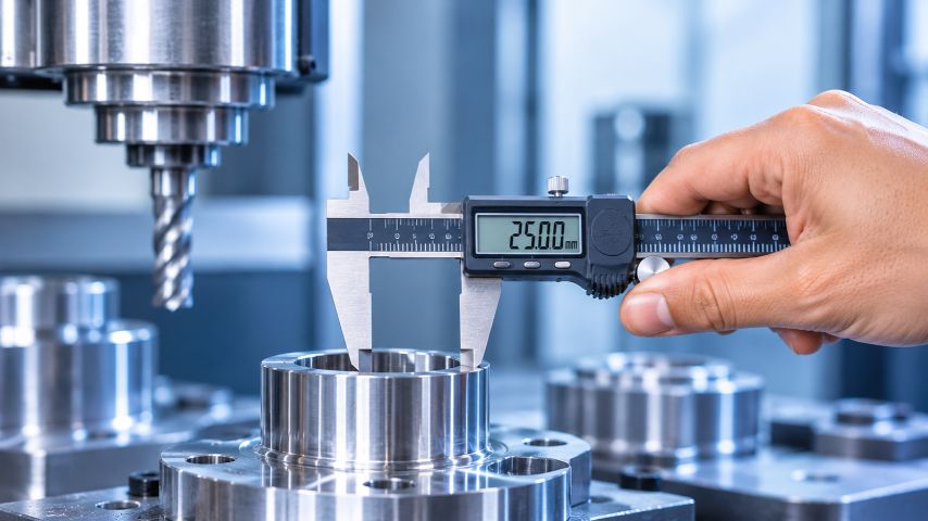
In-process checks happen at the machine, during or between operations. Operators measure critical dimensions at a frequency set in the inspection plan, for example, every tenth part. Common instruments include micrometers, bore gauges, height gauges, and go/no-go plug and thread gauges. Go/no-go gauges give a fast pass-or-fail decision without reading a scale. Some VMCs carry a spindle-mounted touch probe that measures features automatically inside the cycle. Probing can update tool offsets as wear accumulates, holding size across longer runs. Buyers should ask which features get checked in-process, and how often.
Instrument choice must match the tolerance being checked. A common metrology rule of thumb holds that a gauge should resolve about one-tenth of the tolerance band. A ±0.01 mm feature therefore needs an instrument reading to 0.001 mm. Vernier calipers cannot reliably verify such features, even though they appear on many inspection sheets. Measuring hole position accurately usually requires a coordinate measuring machine, or CMM. A CMM uses a precision probe to record points in three dimensions against the drawing’s datums. Buyers should confirm whether a supplier has CMM access in-house or uses an external laboratory.
First Article Inspection and Final Reports
First Article Inspection, or FAI, is a full measurement of the first production part against every drawing requirement. Each characteristic receives a number, usually marked on a ballooned drawing, with the measured value recorded beside it. The report shows the buyer that the process can produce every feature correctly. FAI typically applies to new part numbers, revised drawings, or a process change such as a new fixture. Later batches can then be compared against this baseline. Requesting an FAI report before releasing a production run is a low-cost way to reduce sourcing risk.
Final inspection checks finished parts before dispatch. It usually covers a sample of critical dimensions, visual condition, surface finish, and thread function. Attri Tech Machines’ website describes in-process inspections and final quality checks. The specific instruments, sampling plans, and report formats are not detailed publicly, so buyers should request sample reports during evaluation. Mill test certificates for raw material are a separate document worth requesting where material grade is critical. Buyers needing independent verification can also appoint a third-party inspection agency to witness final inspection before shipment.
Sourcing VMC-Machined Parts: What to Prepare and Expect
A precise inquiry produces a precise quote. Most delays in VMC sourcing start with incomplete drawings or unstated requirements, not with machining itself. This covers what to send, what to ask, and what realistic expectations look like when evaluating a VMC machining company in India or elsewhere for the first time.
Information That Makes a Drawing Quotable
A quotable inquiry includes a 2D drawing with tolerances, plus a 3D model when the geometry is complex. STEP files are widely accepted because most CAM systems import them cleanly. The drawing should state material grade, heat treatment, surface finish, and any coating or plating. General tolerances belong in the title block, with tighter tolerances marked only on functional features. Declared datums and GD&T callouts remove guesswork on positional features. Order quantity and expected annual volume help the supplier choose between simple and dedicated fixtures. Missing items rarely stop a quote, but they add clarification rounds that delay it.
Over-tolerancing is the most common cost driver buyers can control. A tolerance tighter than the function needs forces slower cutting, extra finishing passes, and heavier inspection. It may even push the feature onto a different machine or process. A useful exercise is to review each tight tolerance and ask what fails if it opens slightly. Many drawings carry legacy tolerances copied from older designs. A competent supplier will flag features that look over-specified during quotation review. Attri Tech Machines’ precision parts and components page outlines its drawing-based component work, a useful starting point for such a review.
Capacity, Lead Times and Supporting Documents
Lead time for VMC parts depends on fixture design, programming, prove-out, and machine availability. A simple bracket with standard tooling moves faster than a multi-setup housing needing custom fixtures. Machine count matters too. Attri Tech Machines reports two VMC centers in its published inventory, along with ten CNC turning machines and two wire-cut EDM machines. Buyers with heavy milling requirements should discuss machine loading and scheduling openly. A shop with few VMC spindles can still deliver reliably, but schedules need to be agreed upfront. Asking for a dated delivery plan, rather than a generic lead-time range, improves predictability for both parties.
Documentation should match the part’s risk level. For general engineering parts, a dimensional inspection report and material certificate often suffice. Critical components may justify an FAI report, CMM data, and process photographs. Attri Tech Machines states it holds ISO 9001:2015 certification, a company-reported credential buyers should verify through a current certificate copy. ISO 9001 certifies a quality management system, not the accuracy of any individual part. The company’s published material does not claim sector-specific standards such as aerospace quality systems. Buyers with such requirements should raise them at the inquiry stage rather than assume coverage.
When a Part Needs More Than a Vertical Machining Center
A VMC suits most prismatic parts, but not every feature or tolerance. Recognizing the limits early keeps a project from stalling at prove-out. Sharp internal corners and fine profiles in hardened tool steel often move to wire-cut EDM, which cuts using electrical sparks. Flatness or finish beyond milling capability may require a surface-grinding pass after machining. Round features with tight concentricity usually belong on a lathe instead.
Some geometry calls for different milling equipment. Parts with compound-angle features on many faces may suit a five-axis machine. Heavy multi-face housings in volume often run more efficiently on a horizontal machining center, or HMC, where chips fall freely away from the cut. Buyers should ask whether a supplier owns that equipment or plans to subcontract the work.
Requirements beyond the machine also matter. Regulated sectors may demand sector-specific quality systems, full material traceability or witnessed inspection. Where those apply, buyers should request documentary evidence before ordering and consider an independent inspection agency. Matching the process to the part, rather than forcing the part onto whatever machines are available, remains the most reliable route to conforming components.
Request a VMC Machining Quote From Attri Tech Machines
Send your drawing, 3D model, material, finish, and quantity to Attri Tech Machines for a feasibility review. Ask for the proposed setup, inspection plan, and a sample inspection report. You can also read about the company’s facility and quality background or open the inquiry page.
Attri Tech Machines Pvt. Ltd.
Plot No. 10–11, Gopal Industrial Compound, Meerut Road Industrial Area, Ghaziabad – 201001, Uttar Pradesh, India
Phone: +91 92665 79700
Email: sales@attritechmachines.com
Website: www.attritechmachines.com
Frequently Asked Questions About VMC Machining: Why Most Factories Get This Wrong
What is the difference between CNC turning and CNC milling?
CNC turning rotates the workpiece against a stationary cutting tool, which suits round parts such as shafts, pins and bushes. CNC milling holds the workpiece still while a rotating multi-point cutter moves across it. Milling suits flat faces, pockets and off-center holes. Many components need both, for example, a turned shaft that later receives a milled keyway or flat in a second operation.
What does VMC stand for in machining?
VMC stands for vertical machining center. It is a CNC milling machine whose spindle points vertically down toward the worktable. The word “center” indicates an automatic tool changer, allowing one machine to drill, tap, bore, and mill in a single cycle. Tool magazines on typical VMCs commonly hold around 20 to 30 tools, though capacity varies widely by model and builder.
What tolerances can VMC machining typically hold?
In general industry practice, a well-maintained VMC commonly holds around ±0.025 mm as a standard production tolerance. Values near ±0.01 mm are achievable on selected features with careful fixturing, probing, and temperature control, but cost rises steeply. Material, feature size, and machine condition all affect the result. Buyers should ask which tolerances a supplier routinely holds in production, not its best-case figure.
Is a 3-axis VMC enough for my part?
A 3-axis VMC is usually enough when every feature can be reached from one face, or from two opposite faces with a single flip. Parts with angled holes, undercuts, or tight positional relationships across several faces benefit from a fourth or fifth axis. A quick test: if the part needs three or more re-clamps, ask whether a rotary axis would reduce positional risk.
What materials are commonly machined on a VMC?
VMCs routinely machine aluminum alloys such as 6061 and 6082, mild and alloy steels, stainless steels such as 304 and 316, brass and engineering plastics. Hardened steels above roughly 45 HRC can be milled with suitable carbide tooling, though cycle times lengthen. Attri Tech Machines’ website lists steels, stainless steel, aluminum, brass, and specialized alloys among the materials it works with.
What is the difference between a VMC and an HMC?
A VMC has a vertical spindle above the table, while an HMC, or horizontal machining center, has a horizontal spindle facing the workpiece. HMCs often use pallet changers and a rotating table to machine four sides in one cycle. VMCs cost less, set up faster, and suit most low-to-medium volume prismatic work. HMCs generally justify their cost on high-volume, multi-face housings.
What should a First Article Inspection report for a milled part include?
A First Article Inspection report should list every drawing characteristic with a balloon number, nominal value, tolerance, measured value, and a pass/fail result. It should name the instrument used for each measurement and the drawing revision inspected. For milled parts, true-position and flatness results usually need CMM data rather than hand-gauge readings to be meaningful.
How can I verify a supplier’s VMC capability before ordering?
Start by requesting a machine list showing model, axis configuration, travel envelope, and installation year. Ask for a recent calibration certificate and a sample inspection report from a comparable part. A video walkthrough or plant visit shows machine condition and housekeeping directly. For a first order, a paid sample batch with full inspection data gives the clearest evidence before committing volume.
Can a VMC mill sharp internal corners?
No, because the round cutter leaves a radius in every vertical inside corner. Designers usually accept a radius, add dog-bone relief cuts so square mating parts still seat, or move the feature to wire-cut EDM. A commonly cited design guideline sets corner radius at one-third of cavity depth or more, which keeps the tool stiff.
Which file formats should I send for a VMC machining quote?
Send a PDF drawing showing tolerances, material, and finish, plus a 3D model in STEP format (.stp or .step). IGES files also work but sometimes import with missing surfaces. Native CAD files help only if the supplier runs the same software. Always confirm the drawing revision matches the model revision, since a mismatch is a frequent cause of quoting delays.